Using Pin Multiplexing to Reduce Pin Usage on 8-Bit Microcontrollers
- Marketing Artimar
- 14 de ago. de 2023
- 3 min de leitura
This post will cover two examples of using multiplexing on General Purpose Input/Output (GPIO) pins to reduce a project’s pin usage. The first example uses the technique “Charlieplexing” and the second uses timing peripherals and interrupts to quickly switch between a pin input state and output state to read a pushbutton while driving an LED.

Pin Multiplexing on PIC® and AVR® Microcontrollers
General Purpose Input/Output (GPIO) pins are one of the most important specifications when considering a microcontroller for a design. You need enough pins to connect your microcontroller to all the other components in your design; however, more pins than needed can cause an unnecessary increase in design cost and occupy more space on your board. Additionally, reducing the required number of pins in a design can be the difference between two package sizes in a design. If only there was a way to squeeze just a few more I/O pins out of the smaller one! Fortunately, there are methods to free up pins in such cases.
Here are two examples created by our Microchip applications team using the AVR DD family of microcontrollers. First, we’ll discuss multiplexing GPIO pins to control LEDs through a technique referred to as “Charlieplexing.” Following that, we will look at how to simultaneously run a separate pushbutton and LED using a single pin.
The core idea behind Charlieplexing is to leverage the three states the microcontroller pin can be in: digital HIGH, LOW and high-impedance digital input state (also known as HIGH-Z or Tri-State). By using these three states instead of just the typical HIGH and LOW, the user can use n number of pins to drive up to (n2-n) separate LEDs. In this example, three designated pins would allow for six separate LEDs.
So how exactly does charlieplexing work? To understand that we’ll need to look at an example.

Here we have three I/O pins driving six LEDs.
If we want to turn on just LED 1, we will need to set PA2 HIGH, PA3 LOW and PA4 to HI-Z. Current will flow through LED1 and turn it on whilst leaving all the other LEDs in the off state.

The tri-state is important here because if PA4 was “LOW” instead, it would also turn on LED 5 inadvertently. As shown below:

The high impedance logic state ensures electrical current only travels through LED1. This process may be repeated for any LED in the circuit with the corresponding combination of I/O pin states (the user must have one HIGH, one LOW and the remainder HIGH IMPEDANCE for expected behavior).
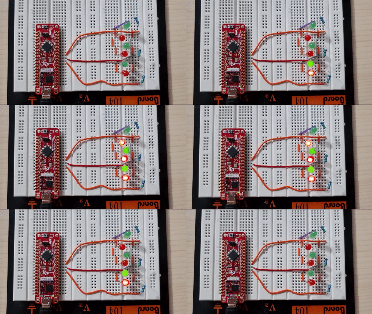
While at any given moment this method only lights one LED, quickly changing I/O states will create the illusion of multiple lit LEDs. (LED dimming works by a very similar principle using Pulse Width Modulation on a single LED). This can be seen below:
The second example involves juggling an LED and a pushbutton on a single pin.
This is accomplished by using interrupts and timers to our advantage. Most of the time the microcontroller pin is driving the LED. However, a timing peripheral will periodically trigger an interrupt inside the microcontroller to quickly switch the pin from an output to an input and then check the status of the pushbutton. While this will temporarily stop driving the LED, if the process can be done quick enough, there is little to no visible effect on the LED while the button’s status is checked.
We use this method in the example below. The microcontroller is driving a blinking LED nonstop while periodically checking the pushbutton and lighting a separate LED if the button is pushed.
While this post only covers the basics of these two techniques, the corresponding GitHub page published by our Microchip applications team contains diagrams, sample code and a much more detailed explanation. Please visit that post and our AVR DD Product Family page to learn more.
Nate Thompson, Alexandru Sabiuta and Microchip Applications, May 30, 2023
Tags/Keywords: Maker, Development Tools


Comentários